


Gharama zake kutokana na ubora wa vifaa kutoka nchi mbalimbali kama.
1.CHINA
Vifaa kutoka China vina ubora wa kawaida ambapo vina uwezo wa kukaa shambani kwa muda wa miaka 3
Gharama zake kwa ekari 1 ni million 1.9 ambapo itajumuisha drip,connectors,water filters,pipes pamoja na Ufundi
2.INDIA
Vifaa kutoka India vina ubora wa kawaida ambapo vina uwezo wa kukaa shambani kwa muda wa miaka 5 bila kuathiriwa na jua.
Gharama yake kwa ekari 1 ni milion 2.5, ambapo itajumisha drip,connectors,water filters,pipes na ufundi.
3. UTURUKI
Vifaa kutoka uturuki vina ubora wa wastani ambapo vina uwezo wa kukaa shambani kwa muda wa miaka 8 bila kuathiliwa na Jua
Gharama yake kwa ekari 1 ni milion 3.5 ambapo itajuimuisha drip,connectors,water filter ,pipes na ufundi.
4. ISRAEL
Vifaa kutoka Israel vina ubora zaidi na vina uwezo wa kukaa shambani kwa muda wa miaka 15 bila kuathiriwa na Jua
Gharama yake kwa ekari 1 ni milion 4.5 ,ambapo itajumuisha drip,connectors,water filter,pipes ,na ufundi.
Pia tutakupatia ushauri wa namna ya kulima kisasa na kuweza kupata mafanikio ya uhakika katika mazao yako.

2 Conveyance, distribution and management structures
3 Field distribution systems
It is not the intent of this guide to be comprehensive with regard to the selection and design of these structures since other sources are available, but it is worthwhile to note some of these structures by way of presenting a larger view of surface irrigation.
The structural elements of a surface system perform several important functions which include:
Most surface irrigation systems derive their water supplies from canal systems operated by public or semi-public irrigation departments, districts, or companies. Some irrigation water is supplied in piped delivery systems and some directly pumped from groundwater.
Figure 7. Typical turnout from a canal or lateral (from walker end Skogerboe, 1987)

2.4.2 Conveyance, distribution and management structures
Conveying water to the field requires similar structures to those found in major canal networks. The conveyance itself can be an earthen ditch or lateral, a buried pipe, or a lined ditch. Lined sections can be elevated as shown in Figure 8, or constructed at surface level. Pipe materials are usually plastic, steel, concrete, clay, or asbestos cement, or they may be as simple as a wooden or bamboo construction. Lining materials include slip-form cast-in-place, or prefabricated concrete (Figure 9), shotcrete or gunite, asphalt, surface and buried plastic or rubber membranes, and compacted earth.
Figure 8. Elevated concrete channel in Iran
Figure 9. Slip-form concrete lining in the USA
The management of water in the field channels involves flow measurement, sediment and debris removal, divisions, checks, drop-energy dissipators, and water level regulators. Some of the more common flow control structures for open channels are shown in Figure 10. Associated with these are various flow measuring devices like weirs, flumes, and orifices. The designs of these structures have been standardized since they are small in size and capacity. Designs for flow measurement and drop-energy dissipator structures need more attention and construction must be more precise since their hydraulic responses are quite sensitive to their dimensions.
Figure 10. On-farm water management structures (from Skogerboe et al., 1971)
a. a simple drop structure

b. a typical check-divider

2.4.3 Field distribution systems
After the water reaches the field ready to be irrigated, it is distributed onto the field by a variety of means, both simple and elaborately constructed. Most fields have a head ditch or pipeline running along the upper side of the field from which the flow is distributed onto the field.
In a field irrigated from a head ditch, the spreading of water over the field depends somewhat on the method of surface irrigation. For borders and basins, open or piped cutlets as illustrated in Figure 11 are generally used. Furrow systems use outlets which can be directed to each furrow.
Figure 11. Head ditch outlets for borders and basins (after Kraatz and Mahajan, FAO, 1975)

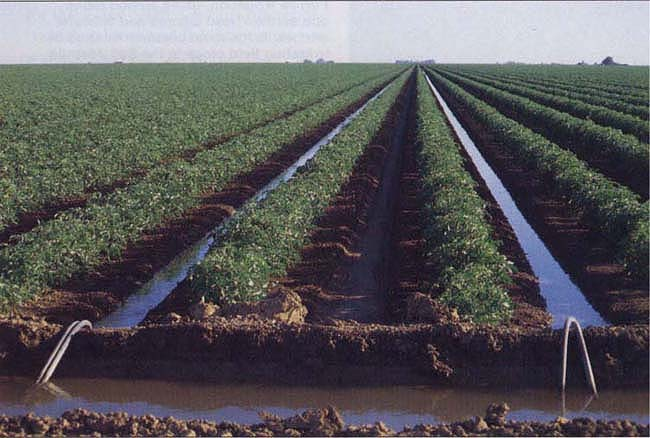
Figure 12 shows a system in which siphon tubes are used as a means of serving each furrow. Field distribution and spreading can also be through portable pipelines running along the surfaces or permanent pipelines running underground. Basins and borders usually receive water through buried pipes serving one or more gated risers within each basin or border. A typical riser outlet, known as an alfalfa valve, is shown in Figure 13. The most common piped method of furrow irrigation uses plastic or aluminium gated pipe like that shown in Figure 14. The gated pipe may be connected to the main water supply via a piped distribution network with a riser assembly like the one shown in Figure 13, directly to a canal turnout, or through an open channel to a piped transition.
Figure 12. Siphons for furrow irrigation
Figure 13. An alfalfa valve riser

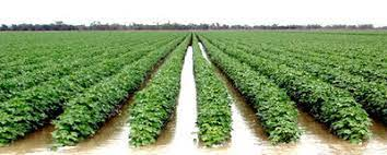
Furrow irrigation avoids flooding the entire field surface by channelling the flow along the primary direction of the field using 'furrows,' 'creases,' or 'corrugations'. Water infiltrates through the wetted perimeter and spreads vertically and horizontally to refill the soil reservoir. Furrows are often employed in basins and borders to reduce the effects of topographical variation and crusting. The distinctive feature of furrow irrigation is that the flow into each furrow is independently set and controlled as opposed to furrowed borders and basins where the flow is set and controlled on a border by border or basin by basin basis.
Furrows provide better on-farm water management flexibility under many surface irrigation conditions. The discharge per unit width of the field is substantially reduced and topographical variations can be more severe. A smaller wetted area reduces evaporation losses. Furrows provide the irrigator more opportunity to manage irrigations toward higher efficiencies as field conditions change for each irrigation throughout a season. This is not to say, however, that furrow irrigation enjoys higher application efficiencies than borders and basins.

There are several disadvantages with furrow irrigation. These may include: (1) an accumulation of salinity between furrows; (2) an increased level of tailwater losses; (3) the difficulty of moving farm equipment across the furrows; (4) the added expense and time to make extra tillage practice (furrow construction); (5) an increase in the erosive potential of the flow; (6) a higher commitment of labour to operate efficiently; and (7) generally furrow systems are more difficult to automate, particularly with regard to regulating an equal discharge in each furrow. Figure 5 shows two typical furrow irrigated conditions.
Figure 5. Furrow irrigation configurations (after USDA-SCS, 1967)
(a) graded furrow irrigation system

(b) contour furrows


A surface irrigation event is composed of four phases as illustrated graphically in Figure 1. When water is applied to the field, it 'advances' across the surface until the water extends over the entire area. It may or may not directly wet the entire surface, but all of the flow paths have been completed. Then the irrigation water either runs off the field or begins to pond on its surface. The interval between the end of the advance and when the inflow is cut off is called the wetting or ponding phase. The volume of water on the surface begins to decline after the water is no longer being applied. It either drains from the surface (runoff) or infiltrates into the soil. For the purposes of describing the hydraulics of the surface flows, the drainage period is segregated into the depletion phase (vertical recession) and the recession phase (horizontal recession). Depletion is the interval between cut off and the appearance of the first bare soil under the water. Recession begins at that point and continues until the surface is drained.
Figure 1. Time-space trajectory of water during a surface irrigation showing its advance, wetting, depletion and recession phases.

The time and space references shown in Figure 1 are relatively standard. Time is cumulative since the beginning of the irrigation, distance is referenced to the point water enters the field. The advance and recession curves are therefore trajectories of the leading and receding edges of the surface flows and the period defined between the two curves at any distance is the time water is on the surface and therefore also the time water is infiltrating into the soil.
It is useful to note here that in observing surface irrigation one may not always observe a ponding, depletion or recession phase. In basins, for example, the post-cut off period may only involve a depletion phase as the water infiltrates vertically over the entire field. Likewise, in the irrigation of paddy rice, an irrigation very often adds to the ponded water in the basin so there is neither advance nor recession - only wetting or ponding phase and part of the depletion phase. In furrow systems, the volume of water in the furrow is very often a small part of the total supply for the field and it drains rapidly. For practical purposes, there may not be a depletion phase and recession can be ignored. Thus, surface irrigation may appear in several configurations and operate under several regimes.
2.1.2 Scope of the guide
The surface irrigation system is one component of a much larger network of facilities diverting and delivering water to farmlands. Figure 2 illustrates the 'irrigation system' and some of its features. It may be divided into the following four component systems: (1) water supply; (2) water conveyance or delivery; (3) water use; and (4) drainage. For the complete system to work well, each must work conjunctively toward the common goal of promoting maximum on-farm production. Historically, the elements of an irrigation system have not functioned well as a system and the result has too often been very low project irrigation efficiencies.
The focus of surface irrigation engineering is at the water use level, the individual irrigated field. For design and evaluation purposes, these guidelines will note elements of the conveyance and distribution system, especially those near the field such as flow measurement and control, but will leave detailed treatment to other technical sources.
Figure 2. Typical irrigation system components (redrafted from USDA-SCS, 1967)
2.1.3 Evolution of the practice
Although surface irrigation is thousands of years old, the most significant advances have been made within the last decade. In the developed and industrialized countries, land holdings have become as much as 10-20 times as large, and the number of farm families has dropped sharply. Very large mechanized farming equipment has replaced animal-powered planting, cultivating and harvesting operations. The precision of preparing the field for planting has improved by an order of magnitude with the advent of the laser-controlled land grading equipment. Similarly, the irrigation works themselves are better constructed because of the application of high technology equipment.
The changes in the lesser-developed and developing countries are less dramatic. In the lesser-developed countries, trends toward land consolidation, mechanization, and more elaborate system design and operation are much less apparent. Most of these farmers own and operate farms of 1-10 hectares, irrigate with 20-40 litres per second and rely on either small mechanized equipment or animal-powered farming implements.
Probably the most interesting evolution in surface irrigation so far as this guide is concerned is the development and application of microcomputers and programmable calculators to the design and operation of surface irrigation systems. In the late 1970s, a high-speed microcomputer technology began to emerge that could solve the basic equations describing the overland flow of water quickly and inexpensively. At about the same time, researchers like Strelkoff and Katapodes (1977) made major contributions with efficient and accurate numerical solutions to these equations. Today in the graduate and undergraduate study of surface irrigation engineering, microcomputer and programmable calculator utilization is, or should be, common practice.
Microcomputers and programmable calculators provide several features for today's irrigation engineers and technicians. They allow a much more comprehensive treatment of the vital hydraulic processes occurring both on the surface and beneath it. One can find optimal designs and management practices for a multitude of conditions because designs historically requiring days of effort are now made in seconds. The effectiveness of existing practices or proposed ones can be predicted, even to the extent that control systems operating, sensing and adjusting on a real-time basis are possible.
2.2 Surface irrigation methods

2.2.1 Basin irrigation
2.2.2 Border irrigation
2.2.3 Furrow irrigation
2.2.4 Uncontrolled flooding
The classification of surface methods is perhaps somewhat arbitrary in technical literature. This has been compounded by the fact that a single method is often referred to with different names. In this guide, surface methods are classified by the slope, the size and shape of the field, the end conditions, and how water flows into and over the field.
Each surface system has unique advantages and disadvantages depending on such factors as were listed earlier like: (1) initial cost; (2) size and shape of fields; (3) soil characteristics; (4) nature and availability of the water supply; (5) climate; (6) cropping patterns; (7) social preferences and structures; (8) historical experiences; and (9) influences external to the surface irrigation system.
2.2.1 Basin irrigation
Basin irrigation is the most common form of surface irrigation, particularly in regions with layouts of small fields. If a field is level in all directions, is encompassed by a dyke to prevent runoff, and provides an undirected flow of water onto the field, it is herein called a basin. A basin is typically square in shape but exists in all sorts of irregular and rectangular configurations. It may be furrowed or corrugated, have raised beds for the benefit of certain crops, but as long as the inflow is undirected and uncontrolled into these field modifications, it remains a basin. Two typical examples are shown in Figure 3, which illustrate the most common basin irrigation concept: water is added to the basin through a gap in the perimeter dyke or adjacent ditch.
Figure 3. Typical irrigated basins (from Walker and Skogerboe, 1987)
a. large basin in the USA
b. paddy basin in Asia
There are few crops and soils not amenable to basin irrigation, but it is generally favoured by moderate to slow intake soils, deep-rooted and closely spaced crops. Crops which are sensitive to flooding and soils which form a hard crust following an irrigation can be basin irrigated by adding furrowing or using raised bed planting. Reclamation of salt-affected soils is easily accomplished with basin irrigation and provision for drainage of surface runoff is unnecessary. Of course it is always possible to encounter a heavy rainfall or mistake the cut-off time thereby having too much water in the basin. Consequently, some means of emergency surface drainage is good design practice. Basins can be served with less command area and field watercourses than can border and furrow systems because their level nature allows water applications from anywhere along the basin perimeter. Automation is easily applied.
Basin irrigation has a number of limitations, two of which, already mentioned, are associated with soil crusting and crops that cannot accommodate inundation. Precision land levelling is very important to achieving high uniformities and efficiencies. Many basins are so small that precision equipment cannot work effectively. The perimeter dykes need to be well maintained to eliminate breaching and waste, and must be higher for basins than other surface irrigation methods. To reach maximum levels of efficiency, the flow per unit width must be as high as possible without causing erosion of the soil. When an irrigation project has been designed for either small basins or furrows and borders, the capacity of control and outlet structures may not be large enough to improve basins.
2.2.2 Border irrigation

Border irrigation can be viewed as an extension of basin irrigation to sloping, long rectangular or contoured field shapes, with free draining conditions at the lower end. Figure 4 illustrates a typical border configuration in which a field is divided into sloping borders. Water is applied to individual borders from small hand-dug checks from the field head ditch. When the water is shut off, it recedes from the upper end to the lower end. Sloping borders are suitable for nearly any crop except those that require prolonged ponding. Soils can be efficiently irrigated which have moderately low to moderately high intake rates but, as with basins, should not form dense crusts unless provisions are made to furrow or construct raised borders for the crops. The stream size per unit width must be large, particularly following a major tillage operation, although not so large for basins owing to the effects of slope. The precision of the field topography is also critical, but the extended lengths permit better levelling through the use of farm machinery.

Joseph Kadeha

James Theodory


